
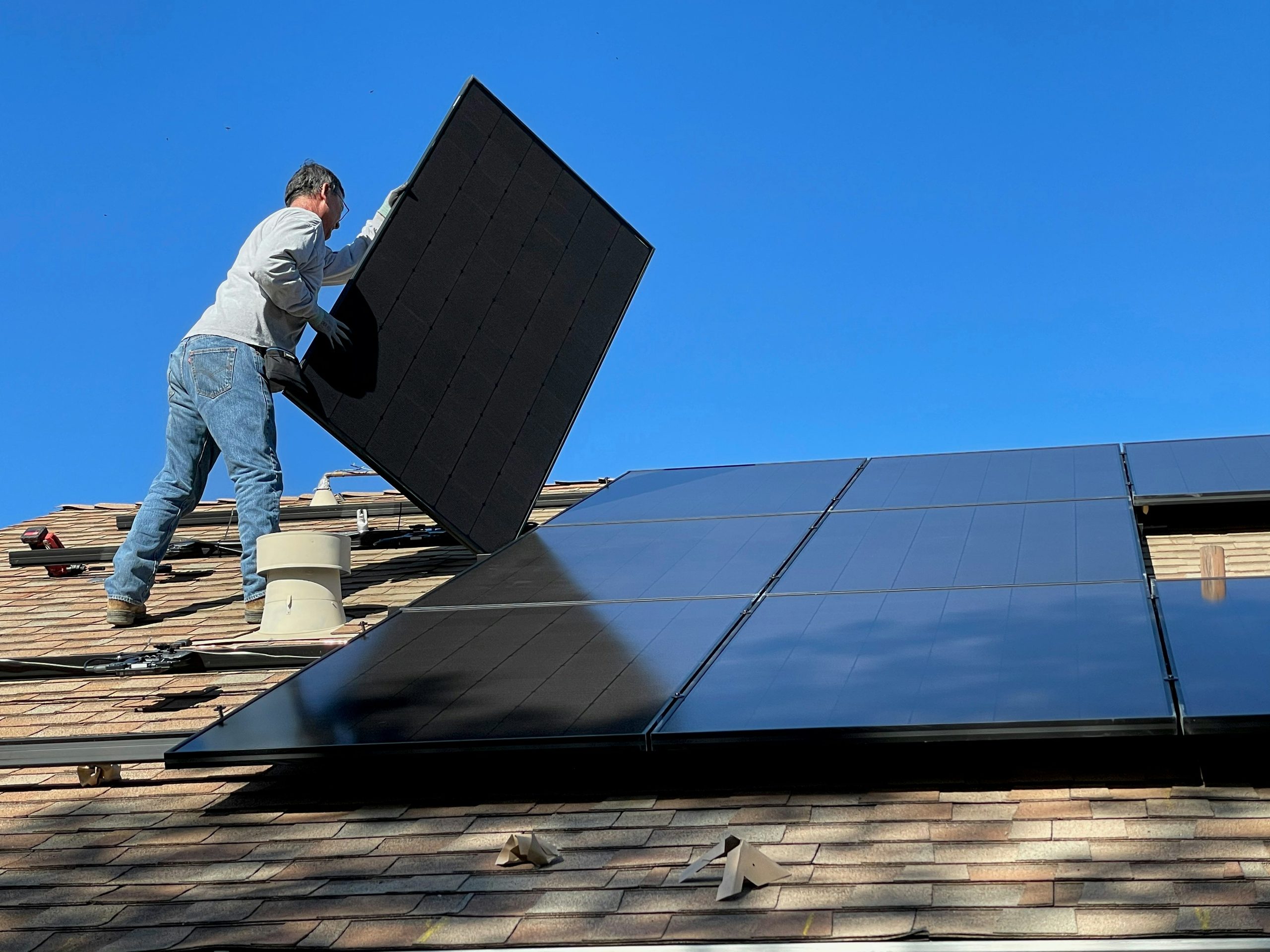
If you buy a “200-watt” portable folding solar panel expecting it to push 200 watts into your battery bank from sunrise to sunset, you are going to be staring at a dying freezer by noon. Out in the real world—away from laboratory flash testers—a flat-lying or hastily propped solar panel under normal atmospheric haze typically delivers 65% to 80% of its nameplate sticker on a clear summer afternoon, and drops to 10% to 25% of its rated wattage under heavy winter overcast[1][2].
Building emergency solar that actually keeps refrigerators, furnace blowers, and emergency radios running through a multi-day blackout comes down to four hard shop rules: sizing your array around winter Peak Sun Hours instead of summer daylight hours, running a true Maximum Power Point Tracking (MPPT) charge controller instead of a cheap PWM box, wiring panels in high-voltage series strings so charging starts early in dim light without cooking your controller on a sub-zero morning, and knowing how to troubleshoot dead strings in the field[3][4].
Safety & Field Disclaimer: Never exceed your solar charge controller’s maximum PV Open-Circuit Voltage (Voc) rating—cold winter temperatures drive open-circuit solar voltage upward by 10% to 15%, which can permanently blow an MPPT controller’s input capacitors on a crisp sub-freezing morning[5][6]. Always install a DC-rated PV disconnect breaker between your solar array and charge controller before servicing wires, use properly rated overcurrent protection within 7 inches of the battery positive terminal, and never charge standard LiFePO4 batteries below 32°F (0°C) unless the battery’s internal heating pads warm the cells first[7][8].
Why Nameplate Wattage Lies to You in the Yard
Every solar panel sold in North America is rated in a temperature-controlled laboratory under Standard Test Conditions (STC): 1,000 watts per square meter (1,000 W/m²) of perpendicular light intensity, an air mass of 1.5, and a solar cell temperature of exactly 77°F (25°C)[2].
You almost never see STC conditions in a real yard or on a roof. As soon as you lay a panel out in the sun, two immediate losses take a bite out of that sticker number before a single electron reaches your charge controller:
First, cell temperature derating cuts output on hot days. Crystalline silicon solar cells lose roughly 0.35% to 0.45% of their power output for every degree Celsius above 25°C (77°F)[1]. On an 85°F summer afternoon, dark solar cells sitting in direct sun routinely bake at 130°F to 145°F (55°C to 63°C)—which immediately knocks 12% to 17% off the panel’s wattage before you even account for dust, screen mesh, or cable losses[2].
Second, atmospheric angle and haze eat another 10% to 15%. Unless you are physically rotating your portable panels every 45 minutes to track the sun across the sky, the sun hits the glass at an oblique angle for most of the day. That is why engineers use the PTC (PVUSA Test Conditions) or NOCT (Nominal Operating Cell Temperature) rating—typically 85% to 88% of the STC sticker—as the realistic baseline for a clean, well-angled panel on a clear day[1].
Peak Sun Hours vs. Daylight Hours
Twelve hours of winter daylight does not equal twelve hours of full solar charging. From 7:30 AM until 10:00 AM, and again after 3:00 PM, the sun sits low enough that its rays pass through a thick slice of atmosphere, delivering only a fraction of the 1,000 W/m² benchmark.
Solar engineers collapse that entire daily bell curve into a single usable number called Peak Sun Hours (PSH)—the equivalent number of hours per day when solar irradiance averages 1,000 W/m²[1][4]. If your area gets 4.0 Peak Sun Hours on a given day, a 100W panel operating at 80% real-world system efficiency will produce roughly 320 Watt-Hours (100W × 4.0 PSH × 0.80) over the entire day, spread across 9 or 10 hours of weak morning, strong midday, and fading afternoon light.
The Field Sizing Equation
To calculate how many nameplate watts of solar panels you actually need to replace yesterday’s battery drain, run this formula using your worst-case winter Peak Sun Hours, not your July averages[1][3]:
Required Solar Array (Watts) = Daily Battery Recharge Needed (Wh) ÷ (Winter Peak Sun Hours × 0.80 System Efficiency)
The 0.80 multiplier accounts for real-world MPPT conversion efficiency (96%–98%), wire voltage drop (2%–3%), dust/pollen film on the glass, and non-tracking fixed tilt angles[3]. If you are charging sealed AGM lead-acid batteries instead of LiFePO4, drop that system efficiency multiplier to 0.65 because lead-acid batteries waste 15% to 25% of incoming charge energy as heat during their slow absorption stage[9][10].
| U.S. Region / Seasonal Condition | Average Summer Peak Sun Hours | Average Winter Peak Sun Hours | Realistic Daily Yield from a 400W Array (LiFePO4 @ 0.80 Eff.) | Realistic Daily Yield from a 400W Array (AGM @ 0.65 Eff.) |
|---|---|---|---|---|
| Desert Southwest (Phoenix, AZ / El Paso, TX) | 6.5 – 7.5 PSH | 4.5 – 5.5 PSH | Summer: ~2,240 Wh / Winter: ~1,600 Wh[1] | Summer: ~1,820 Wh / Winter: ~1,300 Wh |
| Southeast & Gulf Coast (Atlanta, GA / Houston, TX) | 5.5 – 6.0 PSH | 3.2 – 4.0 PSH | Summer: ~1,840 Wh / Winter: ~1,150 Wh[1] | Summer: ~1,495 Wh / Winter: ~935 Wh |
| Midwest & Great Lakes (Chicago, IL / Minneapolis, MN) | 5.0 – 5.8 PSH | 1.8 – 2.5 PSH | Summer: ~1,720 Wh / Winter: ~680 Wh[1] | Summer: ~1,400 Wh / Winter: ~550 Wh |
| Pacific Northwest (Seattle, WA / Portland, OR) | 5.2 – 5.8 PSH | 1.2 – 1.8 PSH | Summer: ~1,760 Wh / Winter: ~480 Wh[1] | Summer: ~1,430 Wh / Winter: ~390 Wh |
| Heavy Overcast / Winter Storm Cloud Deck | ~1.0 – 1.5 PSH | ~0.4 – 0.8 PSH | ~130 – 250 Wh (10%–20% of clear-sky output)[4] | ~105 – 205 Wh |
Two Worked Sizing Scenarios
Scenario 1: Northern Midwest Home Emergency Essentials (Winter Ice Storm)
Suppose you live outside Minneapolis, Minnesota, and need to keep a 15-cubic-foot chest freezer (850 Wh/day), a gas furnace blower fan running intermittently (1,400 Wh/day), and LED lights plus a fiber modem/router (350 Wh/day) alive off a LiFePO4 battery bank. Once you include 10% inverter conversion loss and a 15W inverter idle draw (360 Wh/day), your battery bank loses roughly 3,250 Wh every 24 hours.
In January, Minnesota averages 2.1 Peak Sun Hours on clear days[1]:
- Required Array: 3,250 Wh ÷ (2.1 PSH × 0.80) = 1,935 Watts of solar panels
If you only bought two 200W portable suitcase panels (400W total) because they looked plenty during a July camping test, they will put back roughly 670 Wh on a clear January afternoon—leaving you with a 2,580 Wh daily deficit that empties a 5,000Wh battery bank in less than two days.
Scenario 2: Gulf Coast / Sunbelt Off-Grid Fridge & Comms Setup
Now run the exact same math for a homeowner in central Texas or Georgia keeping a modern kitchen refrigerator (1,200 Wh/day), a CPAP machine without heated humidifier (280 Wh/day), and a GMRS base radio/Wi-Fi router (320 Wh/day) running during a hurricane power outage. Total daily DC battery drain after inverter overhead is 2,200 Wh/day.
In winter, that region averages 3.6 Peak Sun Hours[1]:
- Required Array: 2,200 Wh ÷ (3.6 PSH × 0.80) = 764 Watts of solar panels (four 200W panels)
MPPT vs. PWM Charge Controllers: Why Cheap Controllers Waste 30% of Your Power
A solar charge controller sits between your solar array and your battery bank to step down raw panel voltage and regulate bulk, absorption, and float charging stages[2]. Buying a $25 Pulse Width Modulation (PWM) controller to save money is one of the worst false economies in emergency power.
A PWM controller works like a rapid electronic on/off switch that connects your solar panels directly to the battery terminals[11]. Because a battery acts like a giant voltage clamp, a PWM controller drags the solar panel’s operating voltage down to match whatever voltage the battery currently sits at (typically 12.8V to 14.4V).
Look at what that does to a standard “12V” 200W monocrystalline panel whose electrical label reads Maximum Power Voltage (Vmp) = 19.2V and Maximum Power Current (Imp) = 10.42A:
- On a PWM controller charging a 13.1V LiFePO4 battery, the panel is forced to operate at 13.1V while still capped at its 10.42A current limit: 13.1V × 10.42A = 136.5 Watts. You just threw away 63.5 Watts (31.7% of your panel’s power) as wasted heat inside the controller[11].
- On a Maximum Power Point Tracking (MPPT) controller, an internal high-frequency DC-to-DC buck converter holds the solar panels right at their 19.2V sweet spot (pulling the full 200W) and converts that extra voltage into higher charging amperage at the battery terminals: 200W ÷ 13.1V × 0.97 converter efficiency = 14.8 Amps (194 Watts)[6].
In cold winter weather—when solar cell voltage climbs even higher—an MPPT controller routinely harvests 25% to 35% more daily watt-hours from the exact same panels[11]. Even more importantly, an MPPT controller lets you wire multiple panels in high-voltage series strings (40V to 150V+ DC), which a PWM controller cannot accept without burning out or wasting two-thirds of the array’s power.
Series vs. Parallel Wiring and Wire Gauge Math
How you interconnect multiple panels governs when your system wakes up at dawn, how badly partial tree shade hurts output, and what gauge copper wire you have to buy[3].
Series Wiring (Positive-to-Negative)
Connecting the positive MC4 lead of Panel 1 to the negative MC4 lead of Panel 2 adds their voltages together while keeping current (amps) fixed at a single panel’s rating[3]. Four 200W panels (Vmp 19.2V, Imp 10.42A) wired in 4S (four in series) deliver 76.8V DC at 10.42A (800W).
High string voltage solves two major emergency headaches:
- Early Dawn and Heavy Cloud Wake-Up: Most MPPT controllers require PV input voltage to climb at least 5V above battery voltage before switching on, and 1V above battery voltage to stay running[6]. A single 19V panel under thick storm clouds may sag to 14.5V and drop offline completely, whereas a 76.8V series string sits at 55V–60V even in dim overcast and keeps trickling amps into your batteries all day.
- Low Voltage Drop Over Long Yard Runs: During an outage, you rarely want expensive panels sitting on a dark porch—you want them 50 to 100 feet out in a sunny clearing. Because power loss in a wire scales with the square of current (Ploss = I² × R), pushing 800W at 10.4A (76.8V) instead of 41.7A (19.2V) cuts wire power loss by 16×[3]. A 75-foot one-way run (150 feet round-trip) of 10 AWG pure copper PV wire carries 10.42A at 76.8V with only 1.56V drop (2.0% loss)—whereas carrying 41.7A at 19.2V over that same 10 AWG cable would lose 6.25V (32.5% of your power) just heating up the wire jacket[5].
Parallel Wiring and Hybrid 2S2P Strings
If you wire panels in parallel (joining all positives together and all negatives together using MC4 Y-branch connectors or a fused combiner box), voltage stays at 19.2V while amperage adds up (41.7A for four panels). Parallel wiring isolates shading: if a pine branch casts a shadow across Panel 1, Panels 2, 3, and 4 keep running at 100% output[3]. In a pure series string, heavy shade over one un-bypassed panel drags current down across the entire string.
For four portable panels deployed on ground stands in a yard with scattered trees, wire them in 2S2P (two series pairs of ~38.4V each, joined in parallel at 20.8A). That gives you double the wake-up voltage of a parallel array while ensuring shade on one panel only affects half your array. Whenever you parallel three or more strings, NEC Article 690 requires an inline MC4 fuse or DC breaker (typically 15A or 20A, matching the panel’s maximum series fuse rating) on every positive string lead so a short circuit in one string cannot backfeed full array current into the faulted panel[5].
Cold-Weather Open-Circuit Voltage Math (How Winter Kills Controllers)
The most expensive mistake in winter solar is sizing your series string around the panel’s warm-weather Vmp instead of its freezing-morning Voc (Open-Circuit Voltage)[5][6].
Solar panels behave opposite to batteries in the cold: as ambient temperature drops below 77°F (25°C), solar cell voltage rises. Every UL-listed solar panel prints a Temperature Coefficient of Voc on its back datasheet—typically -0.27% to -0.35% per °C[5]. At sunrise on a sub-zero winter morning—before the MPPT controller starts drawing current—your panels sit at full open-circuit voltage.
Worked Cold-Voltage Calculation:
Suppose you buy four 200W panels rated at Voc = 23.2V at 25°C (77°F), with a Voc temperature coefficient of -0.30%/°C, and wire all four in series (4S) into a popular 100V-rated MPPT controller (such as a Victron SmartSolar 100/50):
- Warm-weather string Voc (77°F / 25°C): 4 × 23.2V = 92.8V (looks safe under 100V).
- Temperature drop on a -4°F (-20°C) morning: A 45°C drop below the 25°C test baseline.
- Voltage increase: 45°C × 0.30%/°C = +13.5% voltage spike.
- Actual winter morning Voc: 92.8V × 1.135 = 105.3 Volts[5].
The instant the sun crests the trees at -4°F, that 105.3V spike punches straight through the 100V MOSFETs and input capacitors inside your charge controller, permanently destroying it on the first cold morning of an outage[6]. Always leave at least a 20% cold-weather Voc headroom margin (keep warm string Voc under 80V on a 100V controller, or step up to a 150V-rated MPPT controller).
Tilt Angle, Snow Shedding & Controller Charging Profiles
Laying portable folding panels flat on a driveway or lawn cuts winter power harvest by 35% to 45% compared to aiming them toward the low winter sun[1].
- Winter Tilt Rule: Set panels facing true magnetic-corrected south at an angle equal to your latitude + 15°—which works out to 45° to 60° across most of the contiguous United States[1]. Steep tilt angles not only catch perpendicular low-angle winter rays, they also help wet snow slide off the tempered glass once the dark cells warm up in morning sun.
- Essential Hardware & Breaker Placement: Wire a non-polarized DC miniature circuit breaker (rated for your string Voc and 1.25× Isc short-circuit current) between the PV array and the MPPT controller so you can safely isolate live solar voltage before disconnecting MC4 plugs—pulling an MC4 connector under load arcs at 80V+ DC and melts the contacts[5][7]. On the battery side of the MPPT controller, install a Class T or MRBF fuse within 7 inches of the battery positive terminal, sized to protect the copper cable gauge (for example, a 60A fuse on 6 AWG 105°C tinned copper wire for a 50A MPPT output)[8].
- Charge Controller Voltage Profiles: Verify that your MPPT controller is programmed to match your exact battery chemistry—14.2V to 14.4V absorption and 13.5V float (with equalization disabled) for 12V LiFePO4 packs, versus 14.6V to 14.8V absorption and 13.6V–13.8V float with temperature compensation enabled for 12V sealed AGM banks[12][13].
Field Failure Modes & Multimeter Troubleshooting
When your solar setup stops charging during an outage, run through these four shop checks with a basic digital multimeter before assuming your panels are dead:
- Zero Amps Into a Cold LiFePO4 Battery: If your MPPT screen shows 75V on the PV input side, 13.1V on the battery terminals, and 0.0A charging current on a freezing morning, your panels aren’t broken—your battery’s internal Battery Management System (BMS) has triggered its 32°F (0°C) low-temperature charging cutoff to prevent irreversible lithium plating on the anode[12][14]. Move the battery inside a heated room or wrap it in an insulated enclosure with a thermostatically controlled heating pad until cell temperature climbs above 35°F.
- Full Voc Voltage, Near-Zero Current Under Load: Unplug the solar string at the PV disconnect breaker and measure Voc across the positive and negative leads with your multimeter. If you read normal open-circuit voltage (e.g., 44V for a 2S string), switch your meter to the 10A DC current port (only on single panels under 10A Isc—never across a high-amperage parallel array) or clamp a DC Hall-effect clamp meter around one lead and briefly short the string leads together in direct sun to verify Short-Circuit Current (Isc)[15]. Normal Voc with near-zero Isc almost always points to a corroded or partially unseated MC4 connector creating high series resistance—cut off the suspect MC4 ends and crimp fresh Stäubli-compatible pins.
- One String Dead in a Parallel Array: If total array amps drop by 50% on a clear midday, check the inline MC4 fuse or combiner breaker on each parallel branch. Portable folding panels stepped on in the grass or pinched in a truck tailgate frequently short internally and pop their string fuse without affecting the healthy branch[5].
- Heavy Overcast Multi-Day Storm Deficit: Under thick winter storm clouds, even a 1,200W solar array produces only 10% to 15% of its rating (120W to 180W)—barely enough to offset an inverter’s idle draw[4]. Solar alone is a fair-weather charger; for true winter grid independence, pair your solar MPPT setup with a compact dual-fuel inverter generator and a high-amp AC battery charger so 90 minutes of generator runtime can top off your LiFePO4 bank when sun disappears for three straight days.
Putting It Into Practice
Build your emergency solar kit around worst-case winter math, not sunny July brochures: multiply your daily watt-hour load by 1.25 (to cover the 0.80 system efficiency factor) and divide by your region’s winter Peak Sun Hours to find the real panel wattage you need[1]. Always spend the extra $60 on a true MPPT charge controller with at least 20% cold-weather Voc headroom, wire panels in 2S or 4S series strings over 10 AWG copper PV cable to beat dawn voltage sag, and prop panels at a steep 45° to 60° southern tilt whenever winter weather hits[6][11].
Technical References & Sources
- National Renewable Energy Laboratory (NREL) – PVWatts Calculator & National Solar Radiation Database (NSRDB): Regional Peak Sun Hours, Cell Temperature Derating, and Tilt Yield Models (2024). ↩
- U.S. Department of Energy (DOE) Solar Energy Technologies Office – Solar Photovoltaic Technology Basics: Standard Test Conditions (STC), Cell Temperature Coefficients, and Charge Regulation (2024). ↩
- Victron Energy – Wiring Unlimited: Series vs. Parallel PV Arrays, Voltage Drop Calculations, and MPPT Sizing Guidelines (2023). ↩
- National Renewable Energy Laboratory (NREL) – Renewable Resource Data Center: Overcast & Seasonal Solar Irradiance Attenuation Data (2023). ↩
- National Fire Protection Association (NFPA) – NFPA 70: National Electrical Code (NEC), Article 690 (Solar Photovoltaic Systems — Cold-Temperature Voc Calculation & String Fusing) & Article 310 (Conductor Ampacity) (2023). ↩
- Victron Energy – SmartSolar MPPT Charge Controller Technical Manual: Cold-Temperature Open-Circuit Voltage Limits & Startup Voltage Thresholds (2024). ↩
- National Fire Protection Association (NFPA) – NFPA 70E: Standard for Electrical Safety in the Workplace — DC Arc Flash & PV Disconnect Standards (2024). ↩
- American Boat and Yacht Council (ABYC) – ABYC E-11: AC and DC Electrical Systems — 7-Inch Overcurrent Protection Rule & Tinned Copper Cable Sizing (2023). ↩
- Epoch Batteries – LiFePO4 vs. AGM Batteries: Round-Trip Charging Efficiency & Absorption Losses (2026). ↩
- Battery University (Cadex Electronics) – BU-804: How to Prolong Lead-Acid Batteries & Absorption Stage Efficiency (2023). ↩
- Morningstar Corporation – PWM vs. MPPT Charge Controller Efficiency Whitepaper: Cold-Weather & High-Voltage Harvest Gains (2023). ↩
- Battle Born Batteries (Dragonfly Energy) – BB10012 12V 100Ah LiFePO4 Battery Datasheet: Absorption/Float Voltage Profiles & Low-Temperature BMS Cutoff (2024). ↩
- Trojan Battery Company – Deep-Cycle AGM Maintenance & Charging Guide: Absorption Voltage & Temperature Compensation (2023). ↩
- Battery University (Cadex Electronics) – BU-410: Charging Lithium-Ion at High and Low Temperatures — Anode Lithium Plating Hazards (2023). ↩
- Fluke Corporation – Digital Multimeter & DC Clamp Meter Troubleshooting Guide for Solar PV Strings (2024). ↩